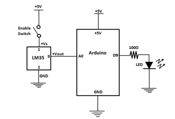
Temperature Monitoring And Prediction System Circuit Diagram Circuit Diagram. In the circuit diagram provided, the system is powered by a 220V power source, which is subsequently regulated by a 12V, 2A power adapter. An Arduino UNO microcontroller serves as the brains of the operation. A 10k thermistor, used as the temperature sensor, is connected to the microcontroller and pulled down by a 10k resistor. This is an industrial level temperature monitoring system and can be used in Plastic Injection Molding machines, Food industries, and so on, where you need to monitor multiple temperature sensors. In this tutorial, we will only cover the monitoring while in version 2 we will make a completely automatic system so that the heaters can be turned
Monitoring temperature and humidity is essential in various applications, such as home automation, greenhouses, industrial settings, and weather stations. This project demonstrates how to build an Arduino-based temperature and humidity monitoring system using a DHT11 sensor and an LCD display to visualize the readings in real-time.

Automatic Temperature Control System using Arduino Circuit Diagram
Temperature sensors are useful in thermometer circuits, temperature compensation applications, as well as a wide array of general purpose applications. The microcontroller can monitor the temperature of each sensor by either reading the temperature data register or functioning as a stand-alone thermostat. The temperature

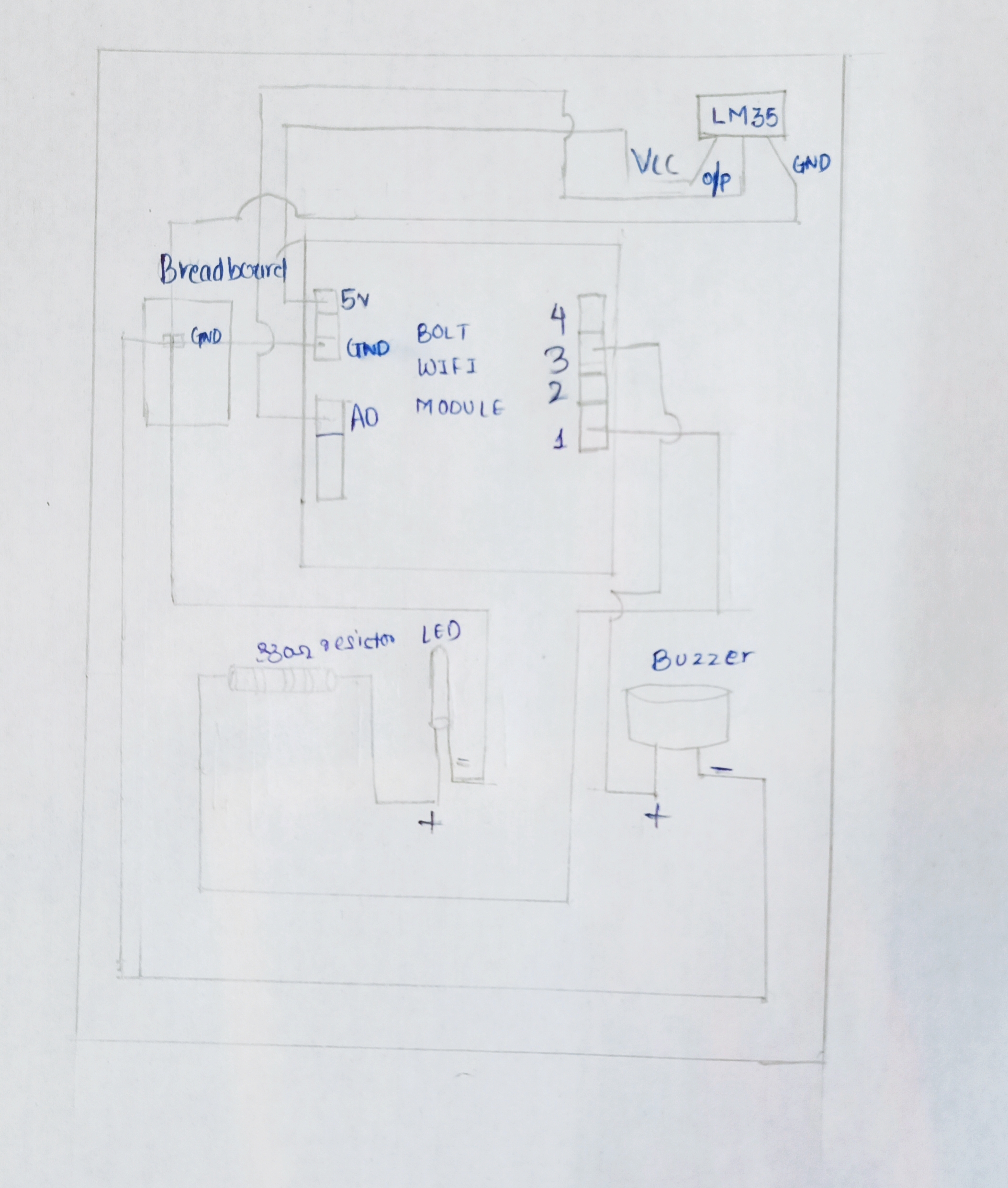
In this tutorial, you will learn how to make a long-range Wireless industrial Temperature monitoring system using Arduino Nano, NRF24L01 Transceiver modules, Industrial temperature sensor capable of measuring the temperature up to 1000 Centigrade, and an I2C supported Oled display Module. Effective temperature and humidity monitoring is critical in industrial enviroments to ensure operational efficiency and equipment longetivity. This project leverages RS485 sensors, Raspberry Pi 5, and Grafana to establish a real-time monitoring system.

PDF Temperature Sensor Design Guide Circuit Diagram
This blog post will show you how to build your very own temperature monitoring system in a step-by-step-fashion. Introduction. To monitor the temperature in one of our netweork equipment cabinets we have made a system based on a cheap small Orange Pi Zero combined with the classic Maxim DS18B20 temperature sensor. Design of the Circuit . Establishing the circuit design involves developing an accurate schematic that connects all its components. Circuit Diagram Overview: Begin with an orderly diagram that clearly depicts all connections. Connecting Temperature Sensor: Connect it directly to one of your microcontroller's input pins. Temperature Sensor